Dissecting The Cisco 881w ISR
- By Joe Astorino
- May 4, 2011
- 13 Comments
Due to some last minute “we need to get this done now even though we have given you no time for design, planning or education” requests at work recently (and they always are right?) I have had the opportunity to dig into the Cisco 881w integrated services router. I learned a lot configuring this device for the given requirements and wanted to share that with you all.
For the uninitiated, the 881w is an “all in one” solution from Cisco aimed at small businesses. It is a Cisco router with a built in switch and a built in wireless AP. The device has five FastEthernet ports. Four of these ports, labeled Fa0 – Fa3 are to be used for your LAN connections while Fa4 is supposed to be for a WAN connection to a broadband provider. The embedded access point can work in both autonomous or light weight mode, and can handle 802.11a/b/g/n. The unit has the option of providing POE on ports Fa0 and Fa1 but requires an optional external power supply to do so.

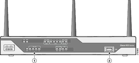
1) LEDs
2) USB Port

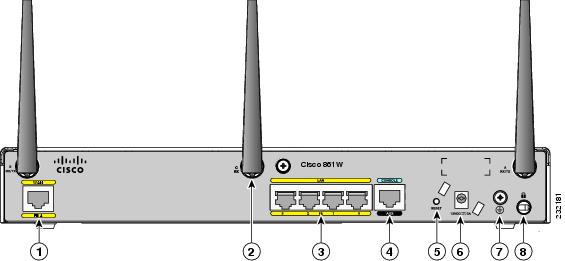
1) WAN Fa4
2) Antennas
3) LAN Fa0 – Fa3
4) Console
5) Reset Button
6) Power
7) Ground
8) Kensington Security Slot
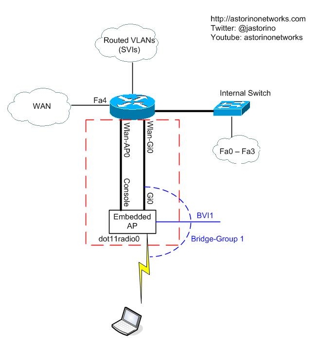
As I started digging around with the 881w, I started finding lots of little things that intrigued me about the design. I had never worked on an all in one unit before, so I was learning as I went along. Figuring out what the various interfaces were quickly became a little bit confusing so I drew out a diagram. Physically, everything is all inside the one box, but logically it looks a little bit more like this. Drawing it out in a logical way really helped me grasp the concepts going on at the CLI. In this blog post we will take a look at the diagram and walk through a few things.
The 881w router is actually more like a layer 3 switch than a router. Like I said, it has four 10/100 ports built right into the unit that you plug end devices into. The built in switch can be segmented into VLANs. Inter-VLAN routing or routing in general is accomplished by switched virtual interfaces (SVI) just like a 3560 or 3750 L3 switch. If you are going to deploy VLANs for network segmentation, just assign your ports to VLANs, create your SVIs, give them IP addresses and away you go.
The wireless portion was what intrigued me the most. When you do a show ip interface brief you will see two interesting interfaces. The first one we will discuss is wlan-ap0. The wlan-ap0 interface is really interesting and cool if you think about it. If you look at the diagram, you see that logically this interface connects to the console port of the embedded AP. You are required to give this interface an IP address, or use ip unnumbered and point it to one of your vlan interfaces. In my case I used ip unnumbered vlan1. So what is the purpose of giving this interface an IP address and what does it do? Well, it gives you IP connectivity to the console of the embedded AP, like an access server. Think of it almost like an aux port on the router physically plugged into the console port of the AP. Another way to look at it is like the router is a Cisco 2509 access server and one of your octopus cables is plugged into the console of the embedded AP. When you telnet to the assigned IP address on a certain port (I think it is 2002) you are redirected to the console of the embedded AP. The other way to connect directly to the console of the AP is with the service-module wlan-ap 0 session command. You issue this command from privileged exec mode on the router itself. Another way to think about this is again with the access server idea. Think about what happens when you are on an access server like a 2509 and you want to get access to the console. You “reverse telnet” to the access-server itself on a certain port and it connects you to the console of some device. Same idea. The service-module command just automates that for you. Once you are actually on the AP console, you have an entirely different configuration. The AP has a completely independent configuration from the router. The AP configuration of course is where you are going to configure your wireless stuff like SSID, encryption, authentication, etc.
The second interesting interface you will see on the router is the Wlan-Gi0 interface. Logically, this interface connects to a GigabitEthernet interface on the embedded AP. Although you can’t see any of this physically, this is your physical connection between the router and the embedded access point. It would be just like if you physically took a cable and ran it from a router into the GigabitEthernet interface of a regular access point. The AP end of this link is referred to as Gi0 in the AP configuration.
So, the AP has an uplink up to the router like we just talked about. It also of course has a radio interface for wireless connections to clients. This interface is called dot11radio0 as shown in the diagram. The somewhat interesting thing about this is that the AP Gi0 interface and the dot11radio0 interface are bridged together into bridge-group 1 by default. This is pretty common for Cisco standalone access points and the same idea exists here. Because the access point passes traffic between wired and wireless interfaces, it needs to bridge the interfaces together. Remember, your embedded AP does not really “route” traffic, it bridges traffic. Routing is handled on your SVI interfaces of the router.
We already talked about how to manage the embedded AP via it’s console port (service-module command) but what if you want to manage it remotely via IP? That is where your BVI interface comes into play. To do this, you configure an IP address on the BVI1 interface. If you are wondering what the BVI technically does behind the scenes, you need to learn a bit about Cisco bridging and the history of it. That is not a light subject. If you just want to get it up and running configure an IP on the BVI interface and be done with it. For the more curious, read on below.
Since the AP is bridging traffic between the wired and wireless interfaces, but you also want it to have IP connectivity at the same time, IRB (integrated routing and bridging) is configured by default. Out of the box you don’t really need to change anything because the bridge-group and BVI interfaces are already configured for you. In fact you are restricted in the CLI from removing bridge-group 1. It has to be there. You also are restricted from removing other key bridging commands. This is probably an effort by Cisco to avoid users screwing things up beyond belief. However, actually understanding what is happening is another story. Traditionally, back in the day you could not bridge and route the same protocol on the same device. For example if you were working with IP you could either bridge it or route it, but not both. CRB came about so you could bridge and route the same protocol on the same device but you still couldn’t communicate between the bridged domain and the routed domain. For example you could have Fa0/0 and Fa0/1 on a router bridging the IP protocol and you could have Fa0/2 routing the IP protocol but the two groups could not communicate between each other which didn’t make it very useful. Integrated routing and bridging (IRB) came about as an evolution to CRB and allows you to bridge and route the same protocol on the same interface. In our 881w IRB allows us to be able to bridge IP traffic between the wired and wireless interfaces but still have layer 3 routed connectivity to the AP itself via the BVI interface. Long story short, the BVI interface is how you communicate via layer 3 to the embedded AP.
If you look at the out of the box configuration of an 881w you will notice some things — Namely, VLAN1 is there by default and the embedded AP bridges gi0 to dot11radio0 and gives you a BVI1 interface to route in and out of your bridge-group. This means that out of the box essentially you have 1 VLAN and that 1 VLAN is bridged so that the wired and wireless are one network. That is all well and good for ma and pa kettles antique shop that wants wireless, but what happens if you want more than one VLAN and you want your wireless traffic segmented from your wired traffic? What if you can’t use VLAN 1 for wireless either? That was the situation I was in.
The requirements of the project were to have VLAN 1 (why they use VLAN 1 is beyond me but whatever) VLAN 2 and VLAN 3 for different wired subnets, while VLAN 4 was to be used for wireless. Logically that means I would have interface vlan1, interface vlan2, interface vlan3 and interface vlan4 on the router itself to handle layer 3 routing. It also means that somehow I needed to pass VLAN 4 traffic between the router and the embedded AP over the Wlan-Gi0 interface. However, because you MUST use bridge-group 1 and BVI1 for AP management, I also had to pass VLAN 1 over the same interface. OK, how do you pass more than one VLAN across a single link? Trunk!
What you can do is this — On the router I configured Wlan-Gi0 as a dot1q trunk so it will pass both VLAN 1 and VLAN 4 down to the embedded AP. On the AP you create sub-interfaces. On the AP I had gi0.1 and gi0.4. Each sub-interface is configured to use dot1q VLAN tagging as well. On the wireless side, you also configure a dot1q sub-interface for each wireless VLAN. In my case wireless was on VLAN 4 so I configured dot11radio0.4 with dot1q tagging as well. Now, remember your wired and wireless interfaces still have to be bridged…so I created bridge-group 4 to bridge gi0.4 and dot11radio0.4 together.
In summary what you have is this — VLANs 1, 2 and 3 and 4 route via the SVIs on the router just like on a L3 switch. VLAN 1 gets passed down over the wlan-gi0 trunk to the AP for management of the AP via BVI1. VLAN 4 also gets passed down the same trunk to the AP where the AP bridges that VLAN to dot11radio0.4 for wireless traffic.
All in all, the 881w is a pretty cool device and it forced me to learn a lot and think about what was going on behind the scenes because …well because I just have to know!
Below you can see some pieces of the final configurations. I will start with the router configuration
interface FastEthernet0
 description VLAN 1 user
 !
!
interface FastEthernet1
 description VLAN 1 user
 !
!
interface FastEthernet2
 description VLAN 2 user
 switchport access vlan 2
 !
!
interface FastEthernet3
 description VLAN 3 user
 switchport access vlan 3
 !
!
interface FastEthernet4
 description ISP Connection
 ip address a.b.c.d e.f.g.h
 no ip redirects
 no ip proxy-arp
 ip virtual-reassembly
 duplex full
 speed auto
 no cdp enable
 !
!
interface wlan-ap0
 description Service module interface to manage the embedded AP
 ip unnumbered Vlan1
 arp timeout 0
 !
!
interface Wlan-GigabitEthernet0
 description Internal switch interface connecting to the embedded AP
 switchport mode trunk
 !
!
interface Vlan1
 description VLAN 1 L3
 ip address 10.10.10.62 255.255.255.192
!
!
interface Vlan2
 description VLAN 2 L3
 ip address 10.10.10.126 255.255.255.192
 !
!
interface Vlan3
 description VLAN 3 L3
 ip address 10.10.10.190 255.255.255.192
!
!
interface Vlan4
 description Wireless VLAN 4 L3
 ip address 10.10.10.254 255.255.255.192
 !
Here is the relevant AP configuration. Note the requirement for my particular implementation was to run the AP in autonomous mode and provide security via WPA2-Personal (PSK). The wireless clients are also 802.11g only so I specifically allow only 802.11b/g radio speeds
dot11 ssid YOURSSID
   vlan 4
   authentication open
   authentication key-management wpa version 2
   wpa-psk ascii terriblepassword
!
!
bridge irb
!
!
interface Dot11Radio0
 description WLAN Physical Radio
 no ip address
 no ip route-cache
 !
 encryption vlan 4 mode ciphers aes-ccm
 !
 ssid YOURSSID
 !
 antenna gain 0
 speed  basic-11.0 basic-12.0 basic-18.0 basic-24.0 basic-36.0 basic-48.0 basic-54.0
 station-role root access-point
 bridge-group 1
 bridge-group 1 block-unknown-source
 no bridge-group 1 source-learning
 no bridge-group 1 unicast-flooding
 bridge-group 1 spanning-disabled
!
interface Dot11Radio0.4
 description WLAN Users VLAN 4
 encapsulation dot1Q 4
 no ip route-cache
 bridge-group 4
 bridge-group 4 subscriber-loop-control
 bridge-group 4 block-unknown-source
 no bridge-group 4 source-learning
 no bridge-group 4 unicast-flooding
 bridge-group 4 spanning-disabled
!
interface GigabitEthernet0
 description the embedded AP GigabitEthernet 0 is an internal interface connecting AP with the host router
 no ip address
 no ip route-cache
 bridge-group 1
 no bridge-group 1 source-learning
 bridge-group 1 spanning-disabled
!
interface GigabitEthernet0.4
 description WLAN Users VLAN 4
 encapsulation dot1Q 4
 no ip route-cache
 bridge-group 4
 no bridge-group 4 source-learning
 bridge-group 4 spanning-disabled
!
interface BVI1
 description AP Management
 ip address 10.10.10.61 255.255.255.192
 no ip route-cache
!
ip default-gateway 10.10.10.62
Hopefully, this gives you a better idea of the Cisco 881w and what the guts of it look like. I hope that by reading this you better understand not only how to configure this device but why certain things are done to make it work internally.
Until next time, keep studying hard
Joe Astorino, CCIE #24347


Excellent, very thorough article. Thanks!
One comment I have is that the BVI1 interface does not need to be on VLAN1, rather on the native VLAN of the trunk.
Have a good one.
Actually, wlan-ap0 is a hardware loopback (you can check this if you enable CDP). For reverse telnet, line 2 is actually used (it is like having the console port of the AP tied to the line 2 instead of the aux line).
You can configure the AP without VLANs and sub-interfaces. Just change the native VLAN on Wlan-GigabitEthernet0 to match the VLAN that you reserved for WiFi (as Cote said previously). Having the Wlan-GigabitEthernet0 configured as trunk, even if you have only one WiFi VLAN, has a positive side effect: all the SVIs on the host router will stay up, even if no computer is attached to the internal switch.
This is the most informative article I found so far on the 881W router. Mine will arrive today and I’m looking forward to replacing my 871W. I’m studying for my CCNA….off and on…and found the 881W on eBay for $200 . I couldn’t resist. I may be calling on you for some guideance if you don’t mind.
This is exactly the information I’ve been searching for and it is presented well too. Anyone starting out on the 881w or similar model needs to read this first.
Thank you!
Great writeup, thanks for taking the time to put it together.
I’m familiar with non-wireless 800 series routers, but didn’t know how the internal AP factored in… Console and Ethernet just like any other standalone AP! Makes perfect sense :-)
This is great information here. I’m having a hell of a time configuring my WiFi on the 881W though. At first, I got the 881W from a friend with no antennas. I copied your command into my config but changed the “YOURSSID” to the SSID I wanted the router to broadcast. Nothing showed up..and 2.4GHz light was just flashing almost at a synchronized rate.
I then thought that it was because I didn’t have any antennas so I bought one (AIR-ANT4941) and it still didn’t solve any problems.
Is there something I’m missing here like if the 2.4GHz light isn’t on solid green then it isn’t broadcasting the SSID or possibly you need all 3 antennas to broadcast? I hate to spend another $20-30 on 2 more antennas to find out my wireless interface is just broken.
Thanks for any help you guys may provide.
Feel free to email me at tjulrich@uncg.edu
[…] than that not so much. These were the two sites I was looking at when trying to set up the 881W. Dissecting The Cisco 881w ISR – Astorino Networks Cisco 880W (881W, 886W, 887W, 888W) Multiple – Dual SSID Integrated Access Point Configuration […]
[…] a futile attempt? The link below is where I went to make sense of the inner workings of the 881W: Dissecting The Cisco 881w ISR – Astorino Networks My configuration is based off of the following link: Cisco 880W (881W, 886W, 887W, 888W) Multiple […]
Great article. thks.
I have a question for my curiosity : why do you configure an “arp timeout 0” on wlan-ap0 interface?
I didn’t, it is a default put in by IOS : )
Hi,
Is it possible to post the entire router config? having some issues..
The 881W is a challenging piece of kit. Too bad Cisco didn’t fit it with gigabit switchports instead of the 10/100 ports. This would have made it perfect.
I find after entering the AP using “service-module wlan-ap 0 session”, the only way back to the router is to use ctrl-c then x. Generally you can’t reenter the AP unless you issue “clear line 2” and confirm. The 1941W routers use line 67.
What is your DHCP setup for the 881W? I can’t seem to get it working on mine.
I hope this helps.
It’s been a very long time, and I don’t have access to one now, but if I am not mistaken, should be pretty boiler plate just like you would do it on an L3 switch